Thursday, November 23, 2023

Draw the path of through glass slab and, hence, to measure the angle of incidence and the angle of image.science practical std 8 to 10

Rays passing through Glass slab


To draw the path of a ray passing through a glass slab and, hence, to measure the angle of incidence and the angle of image.

AIM : To draw the path of a ray passing through a glass slab and, hence, to measure the angle of incidence and the angle of image.

PRINCIPLE: When an oblique ray of light enters from one transparent medium to another transparent medium,  at the surface separating these two media, the light  ray changes its path. This phenomenon is called  refraction of light. When a ray of light passes through  a glass-slab, it is refracted twice, as a result of which, the emergent ray becomes parallel to the incident ray.

APPARATUS :   Glass –slab, Drawing-board, Drawing paper (White),  Foot-rule, Pencil, Pins, Push pins and Protractor.

PROCEDURE :-
Ø  Fix a white drawing-paper on the drawing board using push pins.  Now place the glass-slab on it and mark its position PQRS by drawing its out-line using a pencil.
Ø  Now draw a ray AB such that it is not perpendicular to PQ. Fix two pins upright with separation of 2-3 cm on this ray.
Ø    Now try to see the images of P1 and P2 from side RS and fix pins P3 and P4 upright so that images of P1 and P2 and pins P3 and P4 become collinear at their lower ends.
Ø  Now remove the slab and the pins obtain emergent ray CD by drawing a line passing through marks of P3 and P4, which intersects RS at C.
Ø  Join  B and C to complete the path of the ray. Now draw a normal MN to the surface PQ in such a way that it passes through B. Also draw M’N’, through C to the surface RS.
Ø  Measure ÐAMB (Angle of Incidence) and ÐOCN’ (Angle of Emergence).
Ø  Repeat the experiment for various values of angle of incidence AMB and note your observations in the table.
Glass Slab for Practical
Rays passing through Glass slab
Rays passing through Glass slab Observation table
CONCLUSION :

PRACTICAL USES :
We can study  the path of a ray when it passes through a glass slab. Here emergent ray and incident ray are parallel, but there is some distance between them. This distance depends on angle of incidence, breadth of the slab, and type of material used in the slab. i.e. refractive index of the material. From these information we can have an idea of the refractive index of the material used.

For more details view Video.
Rays passing through Glass slab.

focal length of a concave mirror by obtaining an image of a far distance object, GBSE for std 8 to 10 science practical

Focal length of a concave mirror
     
Focal length


To determine the focal length of a concave mirror by obtaining an image of a far distance object
AIM :- To determine the focal length of a concave mirror by obtaining an image of a far distance object.
APPARATUS  :- A concave  mirror of diameter approximately 10 cm., stand, screen, foot-rule, etc.
PRINCIPLE   :- Rays coming from a far distance object are almost parallel. Such rays, parallel to the principal axis, after being reflected by a concave mirror, are focused at the principal focus of the mirror. Distance between the principal focus and the pole of the mirror is known as the focal length.

NOTE  :  Here screen should be taken small, so that rays coming from the object are not blocked by the screen itself. Diameter of the screen here can be    approximately 3 – 4 cm.
Focal length of Concave mirror
Focal length of Concave mirror,
Focal length of concave mirror Adjustment
Focal Length of Concave mirror
OBSERVATION
Distance between the pole of the mirror and the image on the 
screen = focal-length =                              CM.

CONCLUSION
PRACTICAL USES
Concave mirrors are used in head lights of vehicles, solar furnace, solar cooker, shaving mrror, etc. For all such applcatons it is necessary to know the focal length of the mirror to used. It can be estimated using the given method.

For more details view Video.
Focal length


Friday, October 27, 2023

Post office box, principle of balanced Wheatstone bridge. physics practical std 11 & 12 GSEB

Post Office box
POST OFFICE BOX


Aim:-
A post office box and other necessary instruments are given to you. Take three appropriate ratios of the resistances in the two arms of Post Office Box and determine the values of two unknown resistances.
Now connect the unknown resistances in series and parallel respectively and verify the laws of series and parallel combinations of resistances.

PRINCIPLE :-
It works on the principle of balanced Wheatstone bridge.

APPARATUS :-
A Battery,
unknown resistance (Rx & Ry),
Post Office Box,
a galvanometer,
rheostat,
connecting wires

Post office box Apparatus

CONDITION  1 :- 
Connect unknown resistance      Rx between C and D
Post office line diagram condition 1
Post office condition 1 Practical
 CONDITION 2 :- 
Connect unknown resistance      Ry between C and D
 
Post office line diagram condition 2

Post office condition 2 practical

CONDITION 3 :- 
Connect unknown resistance      Rx & Ry in SERIES between C and D
Post office series connection 
Post office series connection practical
CONDITION 4 :- 
Connect unknown resistance      Rx & Ry in PARALLEL between C and D
Post office parallel connection condition 4
Post office box parallel connection 
Post office box observation table
Post office box calculations
Precautions
(1)   All plug keys of Post Office Box must be tight.
(2)    Contact points of K1 and K2 must be cleaned  with sand paper.
(3)    Galvanometer should be very sensitive.

(4)    Throughout the experiment  press key K2(battery key) first and then key K1(galvanometer key).

For more details view Video.
POST OFFICE BOX

. TO VERIFY THE LAWS OF REFLECTION USING A PLANE MIRROR GSEB Std 8 to 12 Science practical

Reflection of Plain mirror 
Reflection of Plain mirror.


Aim :   To verify the laws of reflection using a plane mirror.

Principle    :  When a ray of light is incident on a reflecting surface, it changes its direction of motion and travels in the original medium following certain laws. This phenomenon is called  reflection of light.

Apparatus : Drawing board, a drawing paper (White), a plane mirror, a foot-rule, a pencil, four pins, four push pins, a protactor, a stand for the plane mirror.

Apparatus : Drawing board, a drawing paper (White), a plane mirror, a foot-rule, a pencil, four pins, four push pins, a protactor, a stand for the plane mirror.
Reflection of Plain mirror Practical
Reflection of Plain mirror
Ø  First of all fix the white drawing paper on the drawing board using push pins.
Ø  First of all fix the white drawing paper on the drawing board using push pins. Place the plane mirror along with its stand and fix its position AB.
Ø  Now draw a line PQ which passes through the mid-point ‘P’ of AB and perpendicular to AB.
Ø  PQ is called the normal to AB.
Ø  Draw a ray RP which makes some angle with the normal (PQ).
Ø  Draw a ray RP which makes some angle with the normal (PQ). On the ray RP fix two pins P1 and P2 vertically with 2-3 cm separation between them. Ray RP is incident ray.
Ø  Now from the other side of PQ , (in which incident ray is not there) see the images of pins P1 and P2 fix other two pins P3 and P4 vertically so that pins P3, P4 and images P1 and P2 appears collinear at their lower ends.
Ø  Now remove the pins and the mirror. Join the marks of P3 andP4 and obtain the reflected ray PS.
Ø  Repeat  the experiment for different angles of incidence. Measure angle of incidence and angle of reflection. Note your reading in the observations table.

Reflection of Plain mirror
Reflection of Plain mirror Observation table
Conclusion : 
Practical uses :  We can study the laws of reflection. We can also study the images obtained by the plane mirror. We can come to know how reflection is used in various optical appliances, e.g., periscope, keleidoscope.

For more details view Video.
Reflection of Plain mirror.

To prepare sulphur dioxide gas in the laboratory Std 8 to 12 Science practical.

Preparation of Sulphur Dioxide in Laboratory


To prepare sulphur dioxide gas in the laboratory. 
AIM :  To prepare sulphur dioxide gas in the laboratory and study its properties.
It is known from the properties of sulphur dioxide that it is extremely pungent smelling colourless bacteriostatic gas. Excess of sulphur dioxide in the air causes air pollution. When it escapes from engine exhaust and factory  chimneys it causes pollution. It is suffocating and leads respiratory inflammation. For this reason it is necessary to reduce  its proportion from the air.
THEORY :  Copper metal and concentrated sulphuric acid reacts to give corresponding  acid salt ( copper sulphate ) and sulphur dioxide gas.
APPARATUS  : Round bottom flask, thistle funnel, delivery tube, four to five gas jars, stand, two-holed cork, lid, wire gauze, tripod stand, etc.

CHEMICALS  : Copper metal, Sulphuric acid, red and blue litmus papers, wax, potassium permanganate, magnesium strip etc.
Preparation of Sulphur dioxide in Laboratory
Observation :- 

Physical properties :
  1. Colour of sulphur dioxide gas :
  2.  Odour or small of sulphur dioxide gas:
  3.  Solubility of the gas in water :
  4.  During the experiment this gas is collected by the upward displacement of air, therefore this gas is                    than air.
Chemical properties :
  1. When red and blue litmus papers are inserted in gas jar containing sulphur dioxide.
  2.  When an ignited magnesium ribbon is held in a gas jar containing sulphur dioxide.
  3.  When potassium permanganate solution is added to the gas jar containing sulphur dioxide.
  4.  Give the chemical reaction, which is used to prepare sulphur dioxide in laboratory.
CONCLUSION :-

PRACTICAL USES
It is known from the properties of sulphur dioxide that it is extremely pungent smelling colourless bacteriostatic gas. Excess of sulphur dioxide in the air causes air pollution. When it escapes from engine exhaust and factory  chimneys it causes pollution. It is suffocating and leads respiratory inflammation. For this reason it is necessary to reduce  its proportion from the air.

For more details View Video:

To prepare sulphur dioxide gas in the laboratory. 

To test the presence of Carbon monoxide and Sulphur dioxide in the atmosphere. Biology std 11 & 12

To test the presence of Carbon monoxide and Sulphur dioxide in the atmosphere.
Test of Carbon  and Sulphur dioxide


INSTRUMENTS
Filter paper,  
Palladium or Platinum chloride, Acidic potasium dichromate.
Test for Carbon monoxide
Filter paper deep in chemical
Keep where transportation is more and smoke of automobiles is very high
View the changes on filter paper.
Slowly slowly it gets change in colour.
After some times 
Finally you see the change in colour that is due to Carbon monoxide is presence in Air.


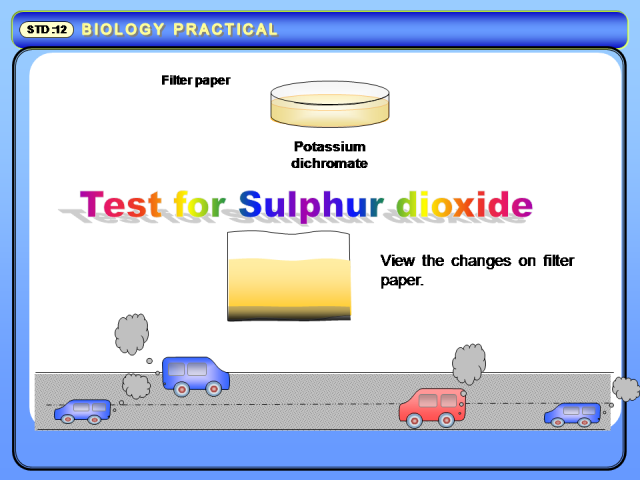
Test for Sulphur dioxide
Filter paper deep in chemical
Keep where transportation is more and smoke of automobiles is very high
View the changes on filter paper.
Slowly slowly it gets change in colour.
After some times 

Finally you see the change in colour that is due to Sulphur dioxide  is presence in Air.


For more details view Video
To test the presence of Carbon monoxide and Sulphur dioxide in the atmosphere.

Angle of deviation of GLASS PRISM, GBSE practical for std 11 & 12.

Angle of Deviation of Glass Prism


ANGLE OF DEVIATION OF GLASS PRISM, 

12.1  AIM :-
Determine with the help of pins, the angle of the given glass prism. Determine the values of angle of emergence and angle of deviation for four different values of angle of incidence. Hence prove that  i + e = A +d.

PRINCIPLE : Reflection and refraction of light.

APPARATUS:  Glass Prism, Drawing paper, Drawing board, Pencil, Ruler, Pin, Protector,

PRECAUTIONS
Ø    While marking the position of a prism with pencil, the prism should not be disturbed.
Ø   A prism should be carefully put back exactly at the marked position.
Ø    While pressing the heads of the pins for fixing them use metal coin or a hard object so that you do not hurt your palm.
Ø    Do not press the pins very hard in the board otherwise it becomes difficult to remove them afterwards.
Ø   See that the pins pushed in the board remain perpendicular to the board.

PROCEDURE :
Take paper and pin it on Drawing board. 
Now take Glass prism and put it on center of Drawing board paper.
Mark the edges of the prism with pencil.
Angle of Deviation of Glass Prism Practical

Draw line P1 M perpendicular  to prism base BC.
Insert two pins vertically P1 & P2..
Place the Prism on its original position.
NOTE :- Pins should be 3 – 4 cm. away from each other.
Observe pins from the side AB and insert two pins P’1 & P’2 such that images of P1 ,P2 and pins P’1 & P’2 are collinear.
Angle of Deviation of Glass Prism Procedure
Draw line Q1 N perpendicular  to prism base BC
Insert two pins verticallyQ1 & Q2.
Angle of Deviation of Glass Prism Procedure
Place the prism on its original position
Observe pins from the side AC and insert two pins Q’1 & Q’2 such that images of Q1 ,Q2 and pins Q’1 & Q’2 are collinear.
Angle of Deviation of Glass Prism Procedure
Measure angle with protector ÐP’1OQ’1.

Angle of PRISM = ÐP’1OQ’1  / 2.
Angle of Deviation of Glass Prism Procedure

For more details view Video
Angle of Prism: