Fill water in a cylinder vessel, connected with a capillary, upto
some height ho. Allow water to flow through capillary in a
controlled way and measure the height (h) of water, in vessel, at regular
intervals (t) of time. Take ten such observations. Draw a graph of h ® t and find the half-life
of the flow of water.
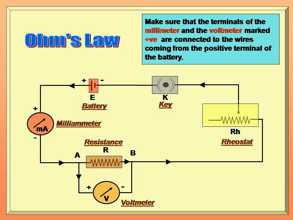
A voltmeter, a current meter, and an unknown resistance etc.
are given to you. Prepare an appropriate circuit to verify Ohm’s law.
With appropriate values of current and
voltages, only with the help of calculations, determine the value of unknown resistance.
PRINCIPLE
Potential difference in a conductor produces electric
current.
APPARATUS :-
A unknown resistance,
a voltmeter (0 - 10 V),
a milliammeter (0 - 500mA), a battery,
a rheostat,
a tap key,
connecting wires.
PRECAUTIONS : -
All the connections must be tight.
Plastic or rubber should not be pressed below the
connecting terminals.
When current does not flow in a circuit the pointer in
both ammeter and voltmeter must be on zero. If it is not so then adjust
the pointer on zero or consider the zero error.
Range of the meters must be appropriate.
Choose a proper scale while plotting the graph so that
the graph is sufficiently large and it occupies most part of the
graph-paper.
To measure the change in chemical reactions and
conclude whether the reaction is exothermic or endothermic.
AIM : To measure
the change in chemical reactions and conclude whether the reaction is
exothermic or endothermic.
THEORY : During the chemical reaction if the
temperature increases the reaction is exothermic and if temperature decreases
the reaction is endothermic.
Aim : To verify
the laws of reflection using a plane mirror.
Principle : When a ray of light is incident on a
reflecting surface, it changes its direction of motion and travels in the
original medium following certain laws. This phenomenon is called reflection of light.
Apparatus : Drawing board, a drawing paper (White), a
plane mirror, a foot-rule, a pencil, four pins, four push pins, a protactor, a
stand for the plane mirror.
Apparatus : Drawing board, a drawing paper (White), a
plane mirror, a
foot-rule, a pencil, four pins, four push pins, a protactor, a stand for the
plane mirror.
Reflection of Plain mirror Practical
Reflection of Plain mirror
Reflection of Plain mirror
Reflection of Plain mirror
Reflection of Plain mirror
ØFirst
of all fix the white drawing paper on the drawing board using push pins.
ØFirst
of all fix the white drawing paper on the drawing board using push pins. Place
the plane mirror along with its stand and fix its position AB.
ØNow
draw a line PQ which passes through the mid-point ‘P’ of AB and perpendicular
to AB.
ØNow
draw a line PQ which passes through the mid-point ‘P’ of AB and perpendicular
to AB.
ØPQ
is called the normal to AB.
ØDraw
a ray RP which makes some angle with the normal (PQ).
ØDraw
a ray RP which makes some angle with the normal (PQ). On the ray RP fix two
pins P1 and P2 vertically with 2-3 cm separation between
them. Ray RP is incident ray.
ØNow
from the other side of PQ , (in which incident ray is not there) see the images
of pins P1 and P2 fix other two pins P3 and P4
vertically so that pins P3, P4 and images P1
and P2 appears collinear at their lower ends.
ØNow
remove the pins and the mirror. Join the marks of P3 andP4
and obtain the reflected ray PS.
ØRepeat the experiment for different angles of
incidence. Measure angle of incidence and angle of reflection. Note your
reading in the observations table.
Reflection of Plain mirror
Reflection of Plain mirror Observation table
Conclusion :
Practical uses : We can study the
laws of reflection. We can also study the images obtained by the plane mirror.
We can come to know how reflection is used in various optical appliances, e.g.,
periscope, keleidoscope. For more details view Video.
To
determine the focal length of a concave mirror by obtaining an image of a far
distance object
AIM :- To
determine the focal length of a concave mirror by obtaining an image of a far
distance object.
APPARATUS
:- A concave mirror of diameter
approximately 10 cm., stand, screen, foot-rule, etc.
PRINCIPLE
:- Rays coming from a far distance object are almost parallel. Such
rays, parallel to the principal axis, after being reflected by a concave
mirror, are focused at the principal focus of the mirror. Distance between the
principal focus and the pole of the mirror is known as the focal length.
NOTE
: Here screen should be taken
small, so that rays coming from the object are not
blocked by the screen itself. Diameter of the screen here can be approximately 3 – 4 cm.
Focal length of Concave mirror
Focal length of Concave mirror,
Focal length of concave mirror Adjustment
Focal Length of Concave mirror
OBSERVATION
Distance between the pole of the mirror and the
image on the
screen = focal-length = CM.
CONCLUSION
PRACTICAL USES
Concave mirrors are used in head lights of
vehicles, solar furnace, solar cooker, shaving mrror, etc. For all such
applcatons it is necessary to know the focal length of the mirror to used. It
can be estimated using the given method. For more details view Video.
To
draw the path of a ray passing through a glass slab and, hence, to measure the
angle of incidence and the angle of image.
AIM
: To draw the path of a ray passing through a glass slab and, hence, to measure
the angle of incidence and the angle of image.
PRINCIPLE: When an oblique ray of light enters
from one transparent medium to another transparent
medium, at the surface separating these
two media, the light ray changes its
path. This phenomenon is called
refraction of light. When a ray of light passes through a glass-slab, it is refracted twice, as a
result of which, the emergent
ray becomes parallel to the incident ray.
APPARATUS
: Glass –slab, Drawing-board, Drawing
paper (White), Foot-rule, Pencil, Pins,
Push pins and Protractor. PROCEDURE :-
ØFix a white drawing-paper on the drawing board
using push pins. Now place the
glass-slab on it and mark its position PQRS by drawing its out-line using a
pencil.
ØNow draw a ray AB such that it is not
perpendicular to PQ. Fix two pins upright with separation of 2-3 cm on this
ray.
Ø Now
try to see the images of P1 and P2 from side RS and fix
pins P3 and P4
upright so that images of P1 and P2 and pins P3
and P4 become collinear at their lower ends.
ØNow remove the slab and the pins obtain
emergent ray CD by drawing a
line passing through marks of P3 and P4, which intersects
RS at C.
ØJoin B
and C to complete the path of the ray. Now draw a normal MN to the surface PQ in such a way
that it passes through B. Also draw
M’N’, through C to the surface RS.
ØMeasure ÐAMB (Angle of Incidence) and ÐOCN’
(Angle of Emergence).
ØRepeat the experiment for various values of
angle of incidence AMB and note your observations in the table.
Glass Slab for Practical
Rays passing through Glass slab
Rays passing through Glass slab
Rays passing through Glass slab
Rays passing through Glass slab Observation table
CONCLUSION :
PRACTICAL USES :
We can study the
path of a ray when it passes through a glass slab. Here emergent ray and
incident ray are parallel, but there is some distance between them. This
distance depends on angle of incidence, breadth of the slab, and type of
material used in the slab. i.e. refractive index of the material. From these
information we can have an idea of the refractive index of the material used. For more details view Video.




.PNG)


